Lewis structures, also called a dot diagram or Lewis model, show the bonding between atoms in a molecule and the existing pairs of electrons. A Lewis structure can be drawn for each covalently bonded molecule, as well as for coordination compounds.
Lewis structures are named after Gilbert Newton Lewis, who introduced them in 1916.
Similar are the diagrams used to represent a dotted electron configuration, where dots represent valence electrons in lone pairs. In addition, they may contain lines representing shared pairs in a chemical bond (single bonds, double bonds, triple bonds, etc.).
Lines are drawn between bonded atoms (pairs of dots can also be used). Excess electrons that form lone pairs are represented by pairs of dots placed next to atoms.
For what Lewis dot structures are used?
A Lewis structure is a graphical representation that shows the molecular geometry of a compound, the bonds that form between the molecules, and the distance between them. These structures show each atom and its position in the molecule's structure using its chemical symbol.
Lewis models are used to represent the number of valence electrons of an element that interacts with other chemical components of the same or another species by forming bonds.
How to draw a Lewis structure?
A central atom must be present to represent the Lewis structure of a molecule. The other elements that constitute the molecule are represented surrounding the central atom.
The central atom should be the least electronegative atom as far as possible, for example, carbon. On the other hand, hydrogen - the smallest element in the periodic table - is always represented as a terminal atom.
The octet rule
The octet rule is a rule that states that atoms bond with each other in order to complete their last shell of the electronic configuration.
This rule determines that stable atoms have eight electrons in their valence shell. Frequently, we can predict the number of bonds an atom can form from the number of electrons needed to reach an octet.
In order to achieve this stability, each atom needs to share, lose or gain electrons in the chemical bonds it forms until it has the required eight electrons in the valence shell.
By drawing a diagram, we will avoid assigning more than eight electrons to each element because every single covalent bond contributes two electrons to each atom in the bond.
Valence electrons
The total number of electrons represented in the Lewis model corresponds to the sum of the numbers of the valence electrons of each atom. By contrast, lone non-valence electrons are not shown. For cations, subtract one electron for each positive charge. For anions, add one electron for each negative charge.
The valence represented in the Lewis structure is the number of electrons in the last energy level of each chemical element when making its electronic configuration.
Once the valence electrons have been determined, they must be located on the diagram. In the case of remaining electrons, they can be used to complete the octet of the central atom. Then, when all the lone pairs of electrons have been placed, the atoms may not obey the octet rule.
All atoms in a diagram must be bonded. We consider a pair of electrons in a Lewis structure to form a bond between two atoms. Just as we consider two atoms to share the same bond pair, the atom that initially had the lone pair still has an octet.
Examples of Lewis structures
In this section, we show some examples of Lewis structures:
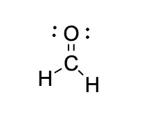
CH2O Lewis structure
The Lewis structure for CH2O has a total number of valence electrons of 12. Therefore, you will need a double bond between the Carbon (C) and Oxygen (O) atoms to complete the octets of all the atoms in the structure.
Let's review our standard valences:
-
Carbon has a valence of 4; 4 outer shell electrons.
-
Oxygen has a valence of 2; 6 outer shell electrons.
-
Finally, hydrogen has a valence of 1; 1 outer shell of electrons.
From this, we can see that carbon will be the central atom. Furthermore, we know oxygen prefers to have a double bond, and giving carbon a double bond to oxygen leaves us with two outer electrons.
The last thing to watch out for is lone pairs; Oxygen has four unbound electrons left in its outer shell so it will have two lone pairs.
Putting all this together, we get this:

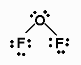
OF2 Lewis structure
Since the difference in electronegativity between fluorine and oxygen is small, it will be a covalent bond.
OF2 Lewis structure is:

As oxygen will be the central atom, and it will have 4 electron pairs around it (two bonding electrons and two non-bonding), these pairs will be distributed tetrahedral. Nevertheless, they will not be considered when determining the geometry, so it will be an angular geometry.
As for the bond angle, although for a tetrahedron, we know that it is 109º, there will be variation in it since the oxygen has free pairs.
The lone pairs exert a greater repulsion than the FO bonds; therefore, these will approach each other, giving rise to a bond angle lower than 109º.
The molecule will be slightly polar since, although the electronegativity difference is slight, the angular geometry will cause some of the components of the dipole moments to add together, giving rise to a non-zero total dipole moment.